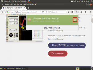
How to create custom tabs in PlanetCNC TNG software

User can create new state tabs.

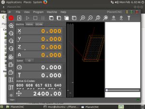
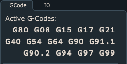
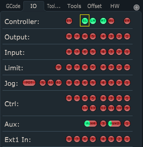
State tabs are displayed on main user interface and can include any parameter used by software whether its tool offset value, number of g-code line or absolute position of machine. By default, software will display only state tabs “GCode” and “IO”.

User can create up to 30 state tabs.

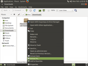
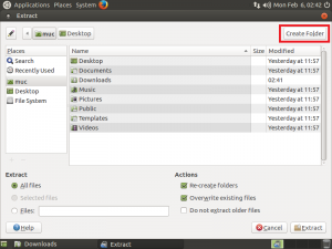
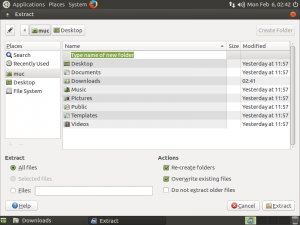
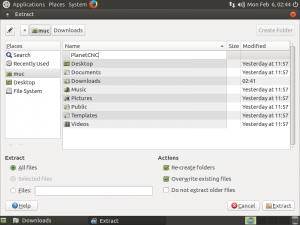
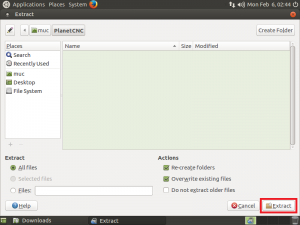
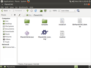
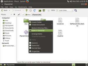
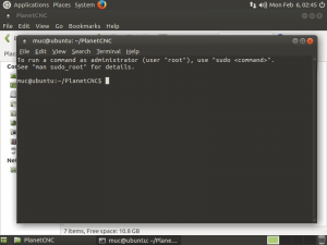
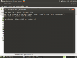
To create new state tab, access your PlanetCNC  install folder and locate Profiles folder. Open your profile folder and create new .txt file and name it State1.txt.

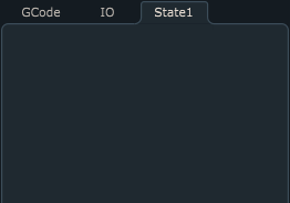
Even when state file is empty, it will be displayed as new state tab, under state panel. Default name of the tab will be its file name, in this case State1:


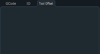
If state panel uses multiple state tabs, it would make sense to use more descriptive tab names. You can do this by simply adding desired <_name text > next to file name.

So, if we would like to change our State1 tab name into e.g.  Tool Offset, change name of the State1 file into: State1_Tool Offset.txt:


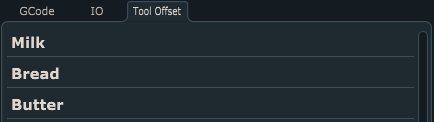
State tabs can be display any given parameter value or text. To display desired text, you can use label command:

label "Milk" 
label "Bread" 
label "Butter"


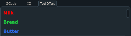
You can also change color of labels using colorname command:

label "Milk" colorname=#f8ff00
label "Bread" colorname=#21d841
label "Butter" colorname=#2c6bed


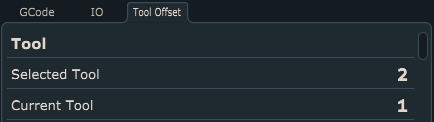
Since we will use tabs to display something more meaningful than shopping list, here is an example of Selected tool and Current tool parameter value display under label Tool:

label "Tool" 
param _selected_tool 0 "Selected Tool"
param _current_tool 0 "Current Tool"


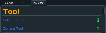
Lets change colors and size of label and parameters:

label "Tool" colorname=#ffa500 size=35
param _selected_tool 0 "Selected Tool" colorname=#2c6bed color=#21d841 
param _current_tool 0 "Current Tool" colorname=#2c6bed color=#21d841 


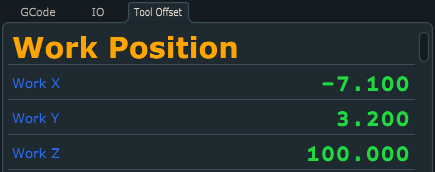
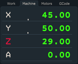
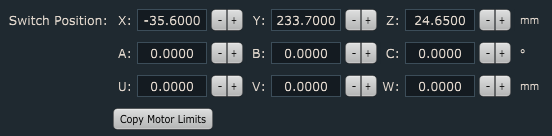
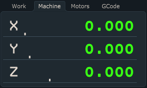
Example of Work Position parameter values displayed under label Work Position, note that position values will be displayed  at three decimals :

label "Work Position" colorname=#ffa500 size=35
param _x 3 "Work X" size=32 colorname=#2c6bed color=#21d841 
param _y 3 "Work Y" size=32 colorname=#2c6bed color=#21d841 
param _z 3 "Work Z" size=32 colorname=#2c6bed color=#21d841


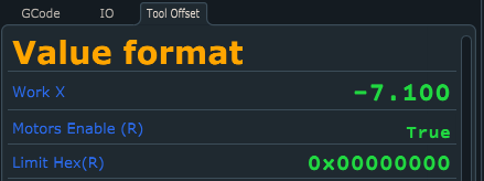
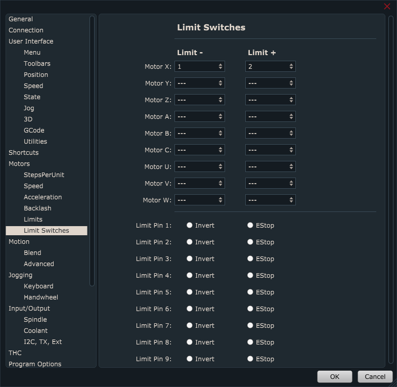
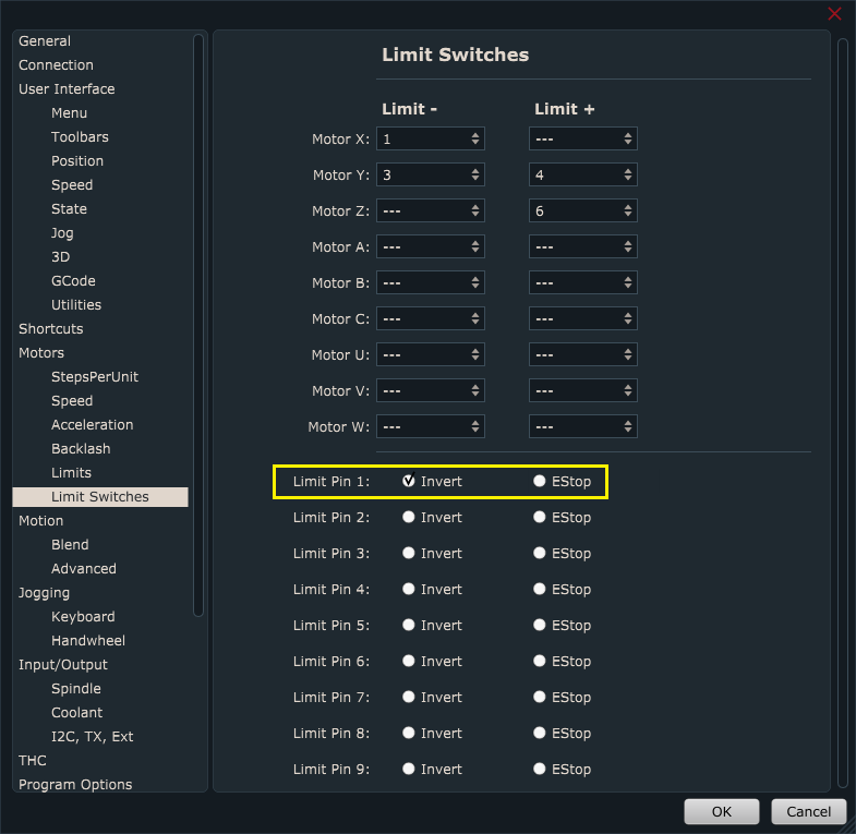
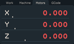
Parameter values can be displayed in decimal, boolean od HEX format. Here is an example of all three types of parameter value format display:

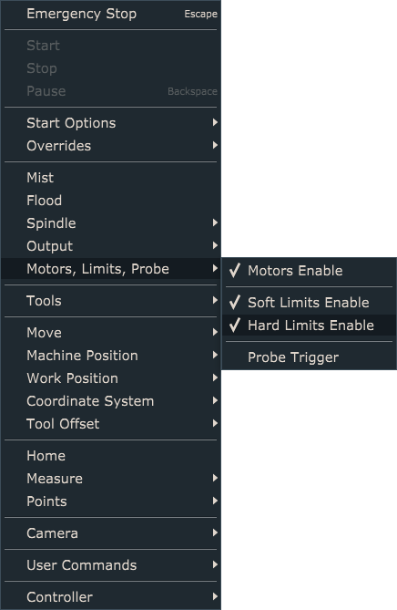
label "Value format" colorname=#ffa500 size=35
param _x 3 "Work X" size=32 colorname=#2c6bed color=#21d841 
param _hw_motors_en B "Motors Enable" colorname=#2c6bed color=#21d841
param _hw_limit X "Limit Hex" colorname=#2c6bed color=#21d841


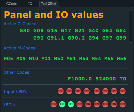
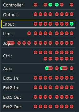
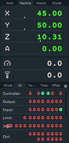
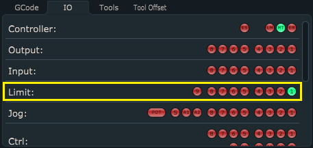
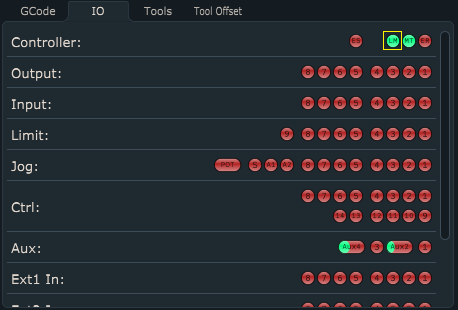
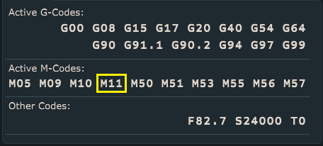
With new state tabs you can also use values of default GCode and IO panels. You can also display controller input/output state values.

label "Panel and IO values" colorname=#ffa500 size=35

panel gcodes colorname=#2c6bed color=#21d841 
panel mcodes colorname=#2c6bed color=#21d841 
panel othercodes colorname=#2c6bed color=#21d841

io input colorname=#2c6bed size=32 name="Input LED's" color=#21d841 
io custom colorname=#2c6bed size=32 name="LED's" led="ES,LM,MT,ER,On,In,Ln,Jn,Cn" color=#21d841


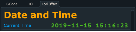
As state tab values you can also use expressions. Here is an example of using DateTime function do display current time:

label "Date and Time" colorname=#ffa500 size=35
expr "DateTime()" DT "Current Time" colorname=#00a5ff color=#4bb725


How to measure work position with movable sensor in PlanetCNC TNG software

This tutorial will explain how to correctly use Work Position / Measure Height  feature with movable sensor using PlanetCNC TNG software and PlanetCNC motion controllers.


Movable Sensor

Movable sensor is basically a switch that sends signal to motion controller corresponding input pin. Software will then calculate Z axis work position zero value, which is usually on the top of the material surface (tool tip just touching the material surface).

The most basic type of movable sensor is usually copper-clad laminate. Clad has soldered wire that is connected to controller sensor input, while GND signal is attached to tool via e.g. crocodile clip. But other switch hardware can be used too (lever switch etc…  ), you just need to configure it correctly in settings.


Example of movable sensor used with Mk3 controller:

Mk3resize


Connecting movable sensor with PlanetCNC motion controller

MK3 controller:


Mk3/4 controller:


MK3DRV controller:


MK3ECO controller:


Configuring movable sensor in  PlanetCNC TNG software

In PlanetCNC TNG under File/Settings/Program Options/Probe & Measure configure input pin that you intend to use for movable tool sensor.

You can select between either Probe 1 or Probe 2 option. It doesn’t matter which one you choose.


Input pin is selected from drop down menu:


Now that your sensor is connected and its input configured, it is best to activate sensor by hand to check if everything is functioning OK. Jog your machine (it can be in any direction) and see if machine stops when you activate sensor. Please note, that sensor dedicated input LED will be ON only when input is activated. If you use normally closed switch for your movable sensor, make sure that you invert its input under File/Settings/Input&Output.

Under IO tab of main display check if input is activated correctly:


Under File/Settings/Program Options/Offsets/Work Position/Measure Height, configure movable sensor parameters:

Speed & Low:

Speed and Low are speed values of first and second work position measurement moves (only Z axis).

First measurement move will be performed at Speed value. After movable sensor is activated, machine retracts for switch click distance and starts with the second measurement move, but this time at Low speed value. Make sure that Speed value is not set too high to the point where movable tool sensor, tool or machine could get damaged. Low value should be significantly lower that Speed value.

Size Z: If you use copper board as a movable sensor, then value of this parameter is the thickness of the copper board( usually 1.6mm).

Switch Click Distance: This is the distance from the point where movable tool sensor is activated and to the point when it is deactivated. For movable sensor this is usually zero. But you can use some small value, in order that software performs second measurement move.

Please note: Make sure that Speed value is not set too high. You see, during measuring procedure, when tool touches the surface (sensor gets activated) machine stops immediately. If your speed is too high, inertia on Z axis may cause loss of steps of Z axis stepper motor.


Work Position/Measure Height with  PlanetCNC TNG software

Work position measure procedure can be executed via menu item Machine/Work Position/Measure Height or  using left toolbar button:

Button


Default sequence of Work Position/Measure Height procedure:

-Machine will start descending at current position in -Z direction using Speed value.

-When sensor is activated, machine will stop and ascend to Z height from which we started Measure Height procedure.

-Software will set new work position offset value

-Z axis work position value on surface of material should now be 0(zero).


Work Position/Measure Height script file

If you would like to edit script code or have more in-depth look at the procedure itself, you can do that by opening script file.

You can access and edit script file in settings under File/Settings/Program Options/Scripts/Work Position/Measure Height and click button Edit Script.


Script file will open in TNG gcode editor. In order that Work Position/Measure Height script file is generated and saved in your profiles Script folder, you need to click Save button.

How to measure tool offset with fixed tool sensor in PlanetCNC TNG software

This tutorial will explain how to correctly use Tool Offset / Measure  feature with fixed tool sensor using PlanetCNC TNG software and PlanetCNC motion controllers.


Fixed tool sensor

For fixed tool sensor we can use a dedicated tool measuring switch or, most basic solution, a standard micro switch fixed to machine table.

When tool activates tool sensor, controllers corresponding input is activated and software sets new tool offset value.

Example of fixed tool sensor used with Mk3 controller:


Connecting fixed sensor with PlanetCNC motion controller

MK3 controller:

InputWiringMk3


Mk3/4 controller:
InputWiringMk34


MK3DRV controller:


MK3ECO controller:


Configuring fixed tool sensor in  PlanetCNC TNG software

In PlanetCNC TNG under File/Settings/Program Options/Probe & Measure configure input pin that you intend to use for fixed tool sensor.

You can select between either Probe 1 or Probe 2 option. It doesn’t matter which one you choose.


Sensor input pin is selected from drop down menu:

Now that your sensor is connected and configured, it is best to activate sensor by hand to check if everything is functioning OK. Jog your machine (it can be in any direction) and see if machine stops when you activate sensor.

Under IO tab of main display check if input is activated correctly:


Now move  machine to position where fixed sensor is mounted. Make sure that tool is right above the center of fixed tool sensor or in case that you use micro switch, above the lever.


Write down Machine coordinates of  X and Y axis. These values will be used for configuration of sensors X and Y axis position:


Jog Z axis towards the sensor. When sensor is activated, write down Machine coordinate of  Z axis. This value will be used for configuration of sensor Z axis position:

We would like to emphasize that it is very important what kind of tool is used when obtaining Z axis position value, because all future tool measurements will be dependent on this value. That is why we call this tool also a default tool. Default tool should not be too long or too short. It should be some normal length.

Signs that your default tool was not suitable are usually Z axis plunging into machine table or Z axis activating limit switch after tool offset measurement.


Under File/Settings/Program Options/Offsets/Tool Offset/Measure Length, insert values that you previously wrote down for Sensor Position X,Y and Z:


Speed & Low:

Speed and Low are speed values of first and second tool offset measurement moves (only Z axis).

First reference move will be performed at Speed value. After fixed tool sensor is activated, machine retracts for switch click distance and starts with the second measurement move, but this time at Low speed value. Make sure that Speed value is not set too high to the point where fixed tool sensor, tool or machine could get damaged. Low value should be significantly lower that Speed value.

Safe Height: After both tool offset measurement moves are finished, machine will ascend to Safe Height value and return to previous position.

Switch Click Distance: This is the distance from the point where fixed tool sensor is activated and to the point when it is deactivated.


Measuring tool offset with  PlanetCNC TNG software

Tool offset measure procedure can be executed via menu item Machine/Tool Offset/Measure Length or  with left toolbar button:

ToolbarButton

Default sequence of Tool Offset Measure procedure:

-Machine will ascend to safe height at current machine position and move to fixed sensors XY position.

-Machine will descend towards fixed tool sensor with Speed value and when sensor gets activated, Z axis will retract for Switch Click Distance and measure tool offset again at Low speed value. Machine will stop and ascend to safe height.

-Software will set new tool offset value

-Machine will return back to XYZ position


Measure tool offset script file

If you would like to edit script code or have more in-depth look at the procedure itself, you can do that by opening script file.

You can access and edit script file in settings under File/Settings/Program Options/Scripts/Tool Offset/Measure Length and click button Edit Script.

Script file will open in TNG gcode editor. In order that Measure Length script file is generated and saved in your profiles Script folder, you need to click Save button.


How to configure limit switch inputs of controller in PlanetCNC TNG software

Limit switches are used for reference (homing procedure) and as a safety feature.

In order that software recognizes limit switch activation and makes appropriate action, we need to configure limit switch inputs in settings: File/Settings/Motors/Limit Switches.

Examples below will demonstrate use of different limit switch wiring methods for X axis. All shown principles can be used for all other axes.


Limit switch input configuration


Example 1: CNC machine uses only one limit switch for X axis (for positive direction), switch is connected to limit input 1:


Example 2: CNC machine uses two limit switches for X axis ( for  positive and  negative direction), both switches are connected to limit input 1:


Example 3: CNC machine uses two limit switches for X axis ( for  positive and  negative direction), each switch is connected to separate limit input, 1 and 2:


Limit switch test:

Test if PlanetCNC TNG software recognizes limit switch activation. On main screen click “IO” tab and observe controllers Limit behavior:


Invert option:
If you use normally closed type of limit switches then you can invert controller limit input in settings: File/Settings/Motors -> Limit Switches

Click radio button next to limit pin that you wish to invert.


At this point, limit switches are connected with controller and PlanetCNC TNG software recognizes limit switch activation.

Limit switches can now be used as reference for purposes of Homing procedure.

In order that limit switches are used also for safety purposes, please follow steps bellow. 


Estop option:

In order that Estop is activated and machine stops during machine operation or jogging (in case of active limit switch), you need to enable its Estop radio button.

If limit switch is activated during program program run, machine will stop and Estop will be activated. If limit switch is activated during machine jogging, machine will stop without Estop.


Enable/Disable of hard limits

To enable hard limit switch stop settings, you need to make sure that they are enabled under: Machine/Motors,Limits,Probe/Hard Limits Enable

You can also use gcode command M11M11 P1 activates hard limits and M11 P0 disables hard limits.


To observe Hard Limits enable/disable state, you can do that by observing:

-Machine/Motors,Limits,Probe/Hard Limits Enable menu. Checked for enabled, unchecked for disabled


-LM light under IO tab which will toggle according to above settings. Green when hard limits are enabled, and red when they are disabled


-M11 mode under Active M-codes state panel. When enabled, M11 is visible, when disabled M11 is not visible.


How to set homing procedure in PlanetCNC TNG software

This tutorial will explain how to correctly use Machine/Home  feature.

Homing procedure will reference machine axes and set machine work area.


First you would need to configure your machines step per unit values, motor & soft limits and limit switch inputs of controller:

How to set step per unit values in PlanetCNC TNG software

How to configure limit switch inputs of controller in PlanetCNC TNG software

How to set motor & soft limits in PlanetCNC TNG software


Homing procedure configuration

Homing procedure is configured in settings: File/Settings/Program Options/Home


Speed & Low:

Speed and Low are speed values of first and second axis reference moves.

First reference move will be performed at Speed value. After limit switch is activated, machine retracts for switch click distance and starts with the second reference move, but this time at Low speed value.

Make sure that Speed value is not set too high to the point where limit switch or machine could get damaged. Low value should be significantly lower that Speed value.


Order:

To set homing order of specified axis, select order number from drop down menu:

Direction:

To set homing direction of specified axis, click radio button of axis direction option, – or +. So, if your Y axis limit switch is mounted at the positive end of Y axis, you enable “+” for Y:

Switch Position:

Switch Position value is axis machine position at which corresponding axis limit switch gets activated. These values, to some degree, have already been obtained in How to set motor & soft limits in PlanetCNC TNG software tutorial.

For example, during Homing procedure when e.g. X axis is being referenced and its limit switch is activated, X axis will get assigned machine position value of Switch Position value.

To automatically populate all axis Switch Position values, click Copy Motor Limits button. However these values are not values of limit switch activation but previously obtained motor limit values…


Obtaining axis switch position values:

Slowly jog Z axis up until Z+ limit switch is hit and machine stops. Write down Z+ axis machine position.

If your X limit switch is mounted at positive end of  X axis: Slowly jog X axis in positive direction until X+ limit switch is hit and machine stops. Write down X+ axis machine position.

If your X limit switch is mounted at negative end of  X axis: Slowly jog X axis in negative direction until X- limit switch is hit and machine stops. Write down X- axis machine position.

If your Y limit switch is mounted at positive end of  Y axis: Slowly jog Y axis in positive direction until Y+ limit switch is hit and machine stops. Write down Y+ axis machine position.

If your Y limit switch is mounted at negative end of  Y axis: Slowly jog Y axis in negative direction until Y- limit switch is hit and machine stops. Write down Y- axis machine position.


Now insert all values that you obtained for switch positions into their corresponding field values…


Move To:

Each axis will travel to its dedicated Move To position immediately after being referenced.  These are machine position values.


Switch Click Distance:

This is the distance from the point where limit switch is activated and to the point when it is released.


Homing sequence:

You can execute homing procedure via Machine menu Machine/Home or left toolbar button: 

When Homing is executed, homing sequence(as set above – see screenshots) will be:

Z axis will be referenced first. Axis will move in positive direction until Z axis limit switch is activated. When switch is activated machine stops and moves to position set with Z “Move To”(Z=10mm) .

X axis will be referenced second. Axis will move in positive direction until X axis limit switch is activated. When switch is activated machine stops and moves to position set with X “Move To”(X=0mm).

Y axis will be referenced third. Axis will move in positive direction until Y axis limit switch is activated. When switch is activated machine stops and moves to position set with Y “Move To”(Y=0mm).


Home script file

Homing procedure uses script file. If you would like to edit script code or to have more in-depth look at the procedure itself, you can do that by opening script file.

You can access and edit script file:

In settings under File/Settings/Program Options/Scripts/Home & Measure -> Home, click button Edit Script.  Script file will open in TNG gcode editor. In order that Home script file is generated and saved in your profiles Script folder, you need to click Save button.


How to set motion limits in PlanetCNC TNG software

This tutorial will explain how to set motion limits of your machine under File/Settings/Motion-> “Range”.

First you need to configure step per unit values, limit switch inputs of controller and motor limits:

How to set Steps Per Unit values in PlanetCNC TNG software

How to configure limit switch inputs of controller in PlanetCNC TNG software

How to set motor limits in PlanetCNC TNG software


If you use normal XYZ axis machine, then we recommend that you set your motion limits to same values as motor limits.

You are probably wondering what is the difference between motor limits and motion limits?
We try to think that motor limits are limiting actual motor movement while motion limits are limiting  effector (tool) movement.

Eleboration:
With use of combined motors and special mechanics you can achieve movement which doesn’t follow the same kinematic rules as linear motion CNC’s. Examples of such machines are H-bot, Delta or multi-axis machines. In such cases values for motor limits and motion limits would not be the same.


To set motion limits of your machine click: File/Settings/Motion-> “Range”


Limit- value sets limitation of effector (tool) movement in negative direction, Limit+ value sets limitation of effector (tool) movement in positive direction for specific axis:


If we want machine to stop when limits are reached we must enable them. To enable motion limits for specified axis enable round button for specified axis:


How to set motor & soft limits in PlanetCNC TNG software

This tutorial will explain how to set motor and soft limits of your machine.

Soft limits (sometimes also program limits term is used) will stop machine motion when motor limit values of specific machine axis are achieved (without any limit switch activation). Soft limits will stop machine in soft stop fashion, meaning axis motors will use deceleration  – hence the name, soft limits.


First you need to configure step per unit values and limit switch inputs of controller:

How to set Steps Per Unit values in PlanetCNC TNG software

How to configure limit switch inputs of controller in PlanetCNC TNG software


Configuring motor and soft limits

You can configure motor limit values for each axis.

Limit- value sets limitation of axis movement in negative direction

Limit+ value sets limitation of axis movement in positive direction

Step 1:

First we need to set all machine and tool offsets values to zero.

Work offset should be set to zero with command “Machine/Work Position/Offset->To Zero”.

Tool offset should be set to zero with with command “Machine/Tool Offset -> To Zero”.


Step 2:

Now we need to choose where machine zero position is. Usually machine works in work position coordinates and it is not really important where machine zero is. What is important is that it is always at same position. I will put some tape to mark it so that you will see it better on image:


Tool is put in spindle and machine is jogged to this position. Use tool with normal length, not too short, not too long. Be careful not to crush tool into machine table when you descent Z axis. You can just loosely tighten tool in spindle and if accident happens nothing will be damaged.

This position should be machine zero. Command for zeroing machine position is in menu: “Machine/Machine Position ->To Zero”.

After using “To Zero” feature you will notice that values under Machine and Motors tab in coordinate position display will be zero for all axes:


Step 3:

Slowly jog Z axis up until Z+ limit switch is hit and machine stops. Step jog in opposite direction so that limit switch is released and write down Z+ axis machine position.

Slowly jog X axis in positive direction until X+ limit switch is hit and machine stops.  Step jog in opposite direction so that limit switch is released and write down X+ axis machine position.

Slowly jog X axis in negative direction until X- limit switch is hit and machine stops. Step jog in opposite direction so that limit switch is released and write down X- axis machine position.

Slowly jog Y axis in positive direction until Y+ limit switch is hit and machine stops.  Step jog in opposite direction so that limit switch is released and write down Y+ axis machine position.

Slowly jog Y axis in negative direction until Y- limit switch is hit and machine stops.  Step jog in opposite direction so that limit switch is released and write down Y- axis machine position.

PLEASE NOTE: Motor limit values obtained above are just an example on how you can obtain and define them. Motor limit values can be any values that suits your machine and application.


Step 4:

Now insert values that you previously written down(X+, X- ; Y+,Y-; Z+)  into Limit windows. If we want motors to stop when limits are reached, we must enable the radio button for desired axis. By doing this, we now set soft limits:

Step 5: Enable/Disable of soft limits

To enable soft limit settings, you need to make sure that they are enabled under: Machine/Motors,Limits,Probe/Soft Limits Enable

To observe Soft Limits enable/disable state, you can do that by observing:

-Machine/Motors,Limits,Probe/Soft Limits Enable menu. Checked for enabled, unchecked for disabled

-SL light under IO tab which will toggle according to above settings. Green when soft limits are enabled, and red when they are disabled

How to set step per unit values in PlanetCNC TNG software

This tutorial will explain how to correctly configure step per unit values of your machine.


Step per unit value (in further text SPU) defines how many step pulses controller needs to generate in order that machine axis moves for distance of one unit. Units can be in millimeters or in inches.

SPU value depends on few factors: stepper motor, stepper drivers micro-step configuration, lead screw pitch:

Motor
Stepper motors usually have 200 or 400 full steps per one rotation of its shaft.
One rotation of shaft in degrees is 360°. For motors with 200 steps per revolution this means
one step is equal to 1.8°. For motors with 400 steps per revolution this means one step is equal to 0.9°.

In equation below, we will name this parameter M

Micro-Stepping
With micro-stepping we improve motors resolution, accuracy, smoother movements, we reduce
resonance problems etc. The real compromise is that as you increase the number of micro-steps per
full step the incremental torque per micro-step drops off drastically. Resolution increases but
accuracy will actually suffer.

With micro-step number we define, how many smaller steps is one full step divided into.
Most common values are ½ , ¼ , ⅛… but it is really up to you which micro-step value you will use.

In equation below, we will name this parameter S

Pitch
Usually CNC machines operate with the help of lead screws and nuts. They can be trapezoidal or
ball screw leads. The pitch of a screw thread is the distance between adjacent threads. When lead
screw is rotated for one revolution, this reflects as linear motion of axis. Distance traveled is equal
to lead screw’s pitch.

In equation below, we will name this parameter P

(Some CNC machines use rack and pinion instead. Distance traveled when pinion makes one
revolution can also be considered as pinion pitch. Similar is also true for toothed belt drive.)


 Configuring SPU values of your machine in PlanetCNC TNG software

StepsPerUnit tab can be found in settings under Motors section: File/Settings/Motors


We can calculate SPU values for our machine by starting from two different initial conditions:

If we know all variable values:
Calculating correct SPU value is easy: SPU value = (M*S)/P

If we don’t know all variable values:
We will have to do some measuring and provide ourselves with some numbers. Then we will be able to calculate correct SPU value.

We use metric units so our unit is millimeter. If you use imperial units (inches) then values are different.

1) In Settings/Axes/Setup we set our SPU value to some “normal” number, say 200 steps per unit.


2) Jog machine to a suitable location, and set: Machine/Work Position/Axis to Zero/XY offsetXY.

3) Now let’s say that we want to move X axis from our offset zero position to X=10 position and measure the actual distance for which machine will move. To measure the distance of machines travel, we can use ruler, caliper or measuring tape which we place under machines tool.

Tool should start at 0 of the ruler:
X0TNG

In MDI window write X10:
MDIx10

Machine should move from X=0 to X=10, therefore travel for 10mm, but when we execute MDI command we can see that machine travelled for 2.5mm instead of 10mm:
X3.5TNG

Meaning, our current SPU value moves machine axis for wrong distance.

4) We can ask ourselves a question:

If ‘Current SPU’ value moves X axis for ‘Measured distance’ value, what is the ‘Correct SPU’ value that will move X axis for ‘Entered distance’ value?

Equation looks like this:
Correct SPU value = ( Current SPU value * Entered distance value ) / Measured distance value

Current SPU = 200
Entered Distance = 10
Measured distance = 2.5

Correct SPU value= (200*10)/2,5 = 800 SPU


Insert correct value for SPU in Settings/Motors/StepsPerUnit:


Now enter X10 in MDI window and measure the new distance value:
X0TNG

Measured distance value is now correct. Our steps per unit are correctly set.
X10TNG

It is recommended to repeat this procedure several times and use largest possible travel. Using 10mm travel is good for first pass but if you use maximum possible distance machine can travel, you will obtain much better results.

Basic PlanetCNC TNG connection settings

PlanetCNC TNG software recognizes all PlanetCNC controllers that are connected to your PC trough USB or Network ports. However, only Mk3 series of controllers (Mk3, MK3/4,MK3DRV,Mk3ECO)  can be used with TNG sw.

It is essential that user sets “Primary controller” in settings. Without this, you will not be able to control your machine!


Basic connection settings

Lets start by going trough connection parameters in settings: File/Settings/Connection

Select the type of connection that you wish to use with your controller: USB or Network.

When you select type of connection, you will notice that window with connected devices will add new controller(s) to the list(beside Simulation). If you have multiple controllers connected via USB to your computer, software will display them. In case of enabling Ethernet option, software will display also controllers connected to computer via network:


To select your primary controller, you need to double click on controller displayed in device list.
“Primary controller” window will now display type of connection, type of controller and its serial number.

Connection light colour description:

Now that your “Primary controller” is selected you can observe its status via connection light.

If you look closely at the bottom right corner of PlanetCNC TNG software, you will notice that there is a round light.
This light can be lit in various colours and each colour indicates different connection, firmware and license status.

Green light with S indicates that PlanetCNC TNG software is in Simulation mode. You can use software options and features, execute gcode programs etc..however, you are not able to control your machine. In order that software communicates with PlanetCNC motion controller, you need to set “Primary controller”. 

Green light indicates that controller is updated with correct firmware version, it is set as primary controller and is activated, meaning license for corresponding controller is found by software. connected_license

Green light with X indicates that controller is updated with correct firmware, it is set as primary controller but software does not find proper license for connected controller. connected_NO_license

Orange light indicates that controllers firmware version is not correct. Update firmware of controller. Firmware_not_correct

Gray light with S indicates no communication between controller and software. Click “Machine/Controller/Reconnect” and make sure that correct controller is set as Primary controller in settings. 

Red light indicates that software is processing commands and is sending them to controller. ProgramRunning

Communication status can also be indicated by observing on-board Link LED. If this LED is blinking in pattern of approximately 500ms, controller is communicating with software. When software is processing commands and is sending them to controller, this LED will be blinking even faster.

If Link LED is not blinking, this indicates communication has dropped.

NEW TNG users: List of essential PlanetCNC TNG tutorials

New to PlanetCNC TNG software? Don’t worry, here you can find list of tutorials that explain how to start using PlanetCNC TNG software as fastest and as effectively as possible.

It is very recommended to follow these tutorials in chronological order:

1. PlanetCNC TNG software overview and performance guidelines
Short description of PlanetCNC TNG software and few guidelines for better perfomance.

2. Updating PlanetCNC controller with PlanetCNC TNG software
To update your PlanetCNC controller with PlanetCNC TNG software you need to follow sequence of steps.

3. PlanetCNC TNG Linux installation guide
PlanetCNC TNG software works also with Linux OS. See how it is installed on Ubuntu MATE.

4. Basic PlanetCNC TNG connection settings

5. Obtaining and activating license for PlanetCNC controller with TNG software

6. How to setup CNC machine in PlanetCNC TNG software

7. Customization of PlanetCNC TNG user interface

PlanetCNC TNG Linux installation guide

We used freshly installed Linux – Ubuntu MATE distribution for this guide. Please note that distributions differ one from another so these steps may not be suitable for all distributions and installation methods may vary.

1.) Start your Ubuntu MATE system.
UbuntuMate 64-bit-2017_UBuntuMATE_Start_01

2.) Using your web browser, download PlanetCNC TNG version from PlanetCNC download page: PlanetCNC TNG download page

UbuntuMate 64-bit-2017_DownloadTNG_02

Under download options choose “PlanetCNC TNG preview-Linux” and click
“Download” button:
UbuntuMate 64-bit-2017_DownloadTNG-SelectLinux_03

3.When download dialogue appears, select “Save File” and hit “OK” button:
UbuntuMate 64-bit-2017_Select folder_04

4.)When download is complete, click “Open folder” button:
UbuntuMate 64-bit-2017_DownloadComplete_05

5.) In “Downloads” folder, right click on downloaded file and click: “Extract To…”:
UbuntuMate 64-bit-2017_ExtractTo_06

6.)Extract dialogue will appear, click: “Create Folder” button:

UbuntuMate 64-bit-2017_ExtractToDirectory_07

7.) Type in the name of new folder: PlanetCNC
UbuntuMate 64-bit-2017_NameDirectory_08

UbuntuMate 64-bit-2017_PlanetCNC_Name_09

8.) Open PlanetCNC folder and click “Extract” button:
UbuntuMate 64-bit-2017_ExtractToPlanetCNC_Folder_10

9.) Extracted files will now populate PlanetCNC folder:
UbuntuMate 64-bit-2017_ExtractedFiles_12

10.) Right mouse click on blank space and click: “Open in Terminal”
UbuntuMate 64-bit-2017_Open_inTerminal_13

11.) Terminal window will appear:
UbuntuMate 64-bit-2017_PlanetCNCTerminal_14

12.) Write: sh install.sh
UbuntuMate 64-bit-2017_TerminalInstall_15

13.) Type in your root password and hit enter.
UbuntuMate 64-bit-2017_PasswordFor_16

14.) PlanetCNC TNG software will automatically launch
UbuntuMate 64-bit-2017_SWStart_17

Obtaining and activating license for PlanetCNC controller with TNG software

We are aware that license is an annoyance. But please understand us.

PlanetCNC TNG software works only with Mk3 series of controllers: Mk3, Mk3/4, Mk3DRVand Mk3ECO.
You cannot use PlanetCNC TNG software with Mk2,Mk2/4, and Mk1 controllers!

To obtain your PlanetCNC TNG license please follow steps below(follow steps very carefully and in exact order):

1.) Update your PlanetCNC USB driver to latest version: Updating to new PlanetCNC USB driver

2.) Update your controller with PlanetCNC TNG software: Updating PlanetCNC controller with PlanetCNC TNG software

3.) When you complete steps 1. and 2., connect your controller with PC, start PlanetCNC TNG software and click Help tab: Help/License Management/Activation Code Generator

You will notice that option “Enable computer” is available. With this feature enabled you are able to select your computer from Device list and generate activation code. We do not accept these activation codes (KU…..).

Select your controller from Device list so that becomes highlighted. “Code” window will be populated with code that starts with “CU…”. Copy this code using right mouse click and select “Copy” or click “Copy to Clipboard”

Send us this code via e-mail when you will request for license. E-mail should also include some sort of proof of license purchase for your controller. Such as invoice, license code used for old software etc…

Your license code will be sent to you via e-mail.
License code will look like this:
LicenseCode

5.) After you receive license code from us, in PlanetCNC TNG software click Help/License Management/Licenses

Click the Import button:
EnterLicenseBlank

Paste the license code that we sent you. You can use right mouse click and select “Paste” or you can use “Paste From Clipboard” button.

EnterLicense

Click OK.
You controller will now appear on the License list:

Software should notify you if license activation has been successful.

You will also notice that green light at the bottom right corner is now without X.

PLEASE NOTE: You cannot use old license with PlanetCNC TNG software as also setting files from old CNCUSB controller software.