New custom buttons can be created and added to the top, bottom, left and right sided toolbars.
Custom buttons can execute any program feature from File, View, Program, Machine and Help menu. Buttons can also execute user commands, use expressions etc..
This makes any program feature, user command, scripted code or custom machine behavior even more accessible and easier to obtain.
Custom toolbar button basics:
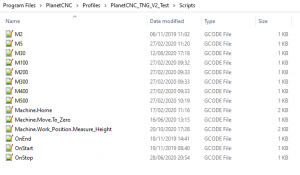
Button files are located in user profile folder. Button files are named: BtnTop.txt, BtnBottom.txt, BtnLeft.txt, BtnRight.txt
Top toolbar user buttons located at the top toolbar will use file: BtnTop.txt
Bottom toolbar user buttons located at the top toolbar will use file: BtnBottom.txt
Left toolbar user buttons located at the top toolbar will use file: BtnLeft.txt
Right toolbar user buttons located at the top toolbar will use file: BtnRight.txt
Buttons are created, configured and designed using dedicated arguments and expressions or functions.
Below is a list or all arguments that can be used in order to create and configure a custom toolbar button. We will try to describe and explain their meaning and use during this tutorial.
Comment:
;
Separators:
—
+++
***
Type:
cmd
expr
py
pythr
plugin
arguments (quoted):
1: command
2: name (optional)
parameters:
name
image
imagechange
stroke
color
size
tooltip
updown
enable
update
val
param
typ
num
Add new program command button to top toolbar:
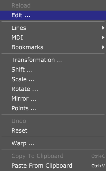
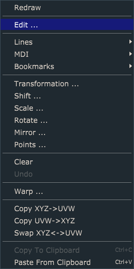
This example will demonstrate how to add new user button to top toolbar which would execute program command from Program menu, in this case, Edit feature:
Open BtnTop.txt file with your text editor. If this file is not yet created, then create new .txt file and name it BtnTop.
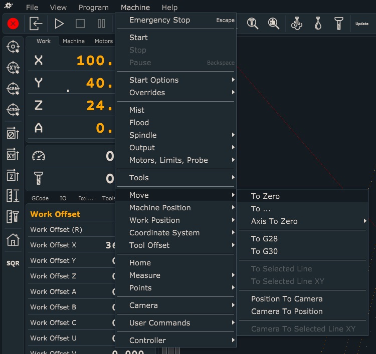
To add button to top toolbar which will execute Program/Edit feature and will use button name “EDIT”, write such line of code:
cmd: "Program.Edit_..." "EDIT"
-Since we will be using button to execute program command we need to use cmd command before the button code.
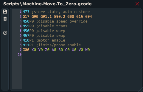
-Code which creates button is actually path to program command location (“Program/Edit …” with difference that level is replaced with “.” and spaces are replaced with “_”)
-To name a button, use one space and put name text into quotes (“name”).
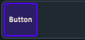
Button will appear at the top toolbar after you restart PlanetCNC TNG software:

Follow steps above in order to create new button for any program command available from menus.
Add new user command button to left toolbar:
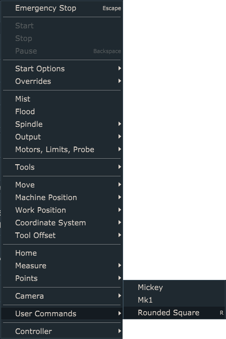
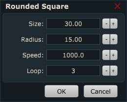
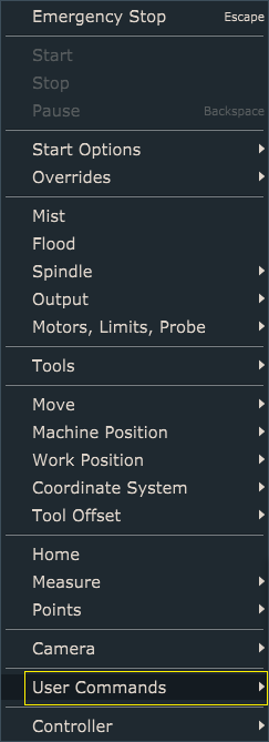
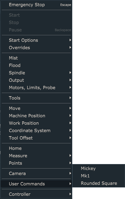
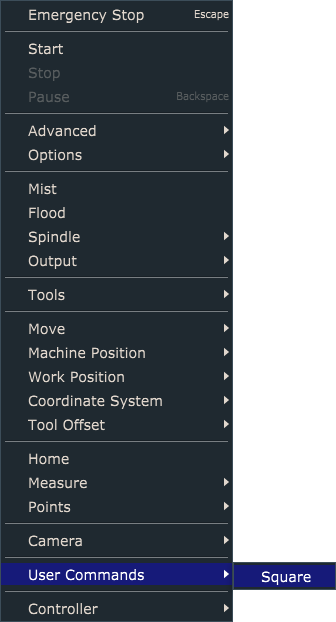
This example will demonstrate how to add button to left toolbar which would execute user command from Machine/User Commands menu, in this case, Square feature:
Open BtnLeft.txt file with your text editor. If this file is not yet created, then create new .txt file and name it BtnLeft.
To add button to left toolbar which will execute Machine/User Commands feature and will use button name “SQR”, write such line of code:
cmd: "Machine.User_Commands.UserCommand_1" "SQR"
-Since we will be using button to execute program command we need to use cmd command before the button code.
-Code which creates button is actually path to program command location (“Machine/User Commands” with difference that level is replaced with “.” and spaces are replaced with “_”):
-User command ID is its menu order number, and since Square is the only user command menu item, its ID is 1.
-To name a button, use one space and put name text into quotes (“name”).
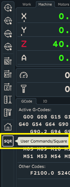
Button will appear at left toolbar after you restart PlanetCNC TNG software:
Adding new button to bottom toolbar with back-light indication
This example will demonstrate how to add button to bottom toolbar which would use expression, hint display and backlight indication.
Attributes suitable for such button behavior would be:
-expr: Type of command used
-enable: Using enable command, user can evaluate any given parameter. When result is true, it enables use of button.
-updown: Using updown argument, user can evaluate any given parameter. When result of it is true, backlight will be active
-updatefast: Using updatefast command, user can evaluate any given parameter. When result is true, it enables prioritized button display refresh rate.
-tooltip: Inserted text will be displayed when cursor hovers over button (hint)
More detailed explanation of button behavior would be:
– button executes custom M-code, M900
– its use is disabled in case of active E-stop
– Backlight is toggled when pressed
-Displayed name of button will be “Button”
– When we hover with cursor over button, hint “MyButton” is displayed
Open BtnBottom.txt file with your text editor. If this file is not yet created, then create new .txt file and name it BtnBottom.
To achieve button behavior described above, write such line of code:
expr: "startcode('M900')" "Button" enable="_hw_estop == 0" updown="_mybutton == 1" update="true" tooltip="MyButton"
-To execute M900 gcode, we will use startcode function. In this case, we need to use expr command at the beginning of the button code.
-To name your button, write desired text between the quotes.
-Button will be enabled only when E-stop is not active. For this purpose we evaluate parameter _hw_estop using the enable command.
-Backlight will be achieved using updown argument. Backlight will be active if user parameter _mybutton is 1(true). To achieve proper parameter manipulation, we wrote suitable code in the M900 gcode file. In this case, simple if…else statement was used. This code within the M900 gcode file, will toggle _mybutton parameter value between 0 and 1.
–Tooltip value displayed will be MyButton.
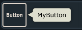
Button will appear at bottom toolbar after you restart PlanetCNC TNG software.
Left image displays button in idle state with tooltip text displayed(mouse cursor hovers over the button), right image displays button in active state and with active backlight:
Customizing buttons icon and color
This example will demonstrate how to add custom button icon for existing user command button .
Button icons use .SVG files which are located in Icons folder of user profile folder. Default .SVG files are already included but you can add your own .SVG files. For this example we will use SVG file “cow.svg”, which was saved in the Icons folder in advance.
Attributes available for such button are:
-image: Using image command, user sets desired image file as new button icon
-stroke: This value will be used as thickness value of button icon
-color: 3 byte hex RGB color value
-imagechange: When true, new icon file will use color shades set with color and stroke values. When false, new icon will keep its original colors and stroke.
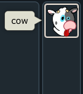
To use cow.svg icon for button without custom color value and tooltip text “COW”, write this code:
cmd: "Machine.User_Commands.UserCommand_1" "" image="Icons/cow.svg" imagechange="False" stroke=1 color=#0ffca0 tooltip="cow"
Button will appear at the right toolbar after you restart PlanetCNC TNG software.
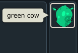
To use cow.svg icon for button with custom color value and tooltip text ” GREEN COW”, write this code:
cmd: "Machine.User_Commands.UserCommand_1" "" image="Icons/cow.svg" imagechange="True" stroke=1 color=#0ffca0 tooltip="green cow"
Button will use light green shade set with color value and tooltip text green cow:
Additional examples of custom toolbar buttons
I will describe few more examples of buttons that have same effect more or less, but each with a different approach.
Since there were a lot of requests on how to activate controllers output pins and ExtInOut board outputs, these examples will mainly focus on these.
Buttons for activation (ON) of output pins 1-4:
Example 1: Using _output and _output_num parameters:
expr: "_output_num|1=1" name="OUT1" updown="_output==1" update="true"
;expr: "_output_num|1=1" -> Sets controller output pin 1 to 1(high). For this we use parameter _output_num, which is an index parameter.
;Meaning, _output_num also needs index value(number of output pin we want to activate).

;updown="_output==1"     -> Button will have active backlight when _output parameter value will be equal to 1.

expr: "_output=2" name="OUT2" updown="_output==2" update="true"
;expr: "_output=2" -> Sets _output parameter value to 2( this sets second output pin to 1), mind that all output other pin values are at 0.
;updown="_output==2" update="true" -> Button will have active backlight when the _output register value will be equal to 2.

expr: "_output=4" name="OUT3" updown="_output_num|3" update="true"
;expr: "_output=4" -> sets _output parameter value to 4(this sets third output pin to 1), mind that all other output pin values are at 0.
;updown="_output_num|3" update="true" -> Button will have active backlight when the third output pin will be 1(high).

expr: "_output=8" name="OUT4" updown="_output_num|4" update="true"
Example 2: Using _output ,_output_num parameters and bitwise OR binary operator:
expr: "_output= _output | 1" name="OUT1" updown="_output_num|1" update="true"
; _output= _output | 1 -> by using OR bitwise operator, we can set the first output pin of _output parameter. Make sure to use the space before and after the "|" symbol
; updown="_output_num|1" update="true" -> Button will have active backlight when the first output pin will be 1(high).

expr: "_output= _output | 2" name="OUT2" updown="_output_num|2" update="true"
expr: "_output= _output | 4" name="OUT3" updown="_output_num|3" update="true"
expr: "_output= _output | 8" name="OUT4" updown="_output_num|4" update="true"
Example 3: Using expression function out(). When using expression function out(), zero based numbering is used (1st pin has number zero, 2nd pin has number one etc…)
expr: "out(0,1)" "OUT1" updown="_output_num|1" update="true"
;expr: "out(0,1)" -> sets the first output pin to 1. First argument of out() function is output pin number, second is output value.
;updown="_output_num|1" update="true" -> Button will have active backlight when the first output pin will be 1(high).

expr: "out(1,1)" "OUT2" updown="_output_num|2" update="true"

expr: "out(2,1)" "OUT3" updown="_output_num|3" update="true"

expr: "out(3,1)" "OUT4" updown="_output_num|4" update="true"
Buttons for deactivation (OFF) of output pins 1-4:
Example 1: Using _output and _output_num parameters:
expr: "_output_num|1=0" name="OFF1"
;expr: expr: "_output_num|1=0" -> sets first output pin to 0.
expr: "_output_num|2=0" name="OFF2"
;expr: expr: "_output_num|2=0" -> sets second output pin to 0.
expr: "_output_num|3=0" name="OFF3"
;expr: expr: "_output_num|3=0" -> sets third output pin to 0.
expr: "_output_num|4=0" name="OFF4"
;expr: expr: "_output_num|4=0" -> sets fourth output pin to 0.
expr: "_output=0" name="ALL"
;expr: "_output=0" -> sets whole _output parameter value to 0. This means, if you would have other active outputs, this expr will reset all of them.
Example 2: Using _output parameter and bitwise AND and NEGATION unary operator:
expr: "_output= _output & ~1" name="OFF1"
;"_output= _output & ~1" -> by using bitwise AND and NEGATION operator, we reset the first output pin of _output parameter.

expr: "_output= _output & ~2" name="OFF2"

expr: "_output= _output & ~4" name="OFF3"
;"_output= _output & ~4" -> by using bitwise AND and NEGATION operator, we reset the fourth output pin of _output parameter.

expr: "_output= _output & ~8" name="OFF4"

expr: "_output= _output & ~_output" name="ALL"
;expr: "_output= _output & ~_output -> sets whole _output parameter value to 0. This means, if you would have other active outputs, this expr will reset all of them.
Example 3: Using expression function out(). When using expression function out(), zero based numbering is used (1st pin has number zero, 2nd pin has number one etc…)
expr: "out(0,0)" "OFF1"
;expr: "out(0,0)" -> resets the first output pin to 1. First argument of out() function is output pin number, second is output value.
expr: "out(1,0)" "OFF2"

expr: "out(2,0)" "OFF3"

expr: "out(3,0)" "OFF4"
Buttons for toggling of output pins 1-4:
Example 1: Using _output and _output_num parameters and bitwise AND,OR and NEGATION unary operator:
expr: "if(_output & 1,_output= _output & ~1,_output= _output | 1)" name="OUT1" updown="_output_num|1" update="true"
;expr: "if(_output & 1,_output= _output & ~1,_output= _output | 1)" -> If.. statement uses three arguments.
;First argument is condition, which when true, executes second arg. If first arg is not true, third arg is executed.
;So, with _output & 1 (arg1) we check if first output pin is already active, if it is, we reset it using _output= _output & ~1(arg2). If first output is not active, we set it with
_output= _output | 1(arg3).

expr: "if(_output & 2,_output= _output & ~2,_output= _output | 2)" name="OUT2" updown="_output_num|2" update="true"

expr: "if(_output & 4,_output= _output & ~4,_output= _output | 4)" name="OUT3" updown="_output_num|3" update="true"

expr: "if(_output & 8,_output= _output & ~8,_output= _output | 8)" name="OUT4" updown="_output_num|4" update="true"
Example 2: Using command type cmd and Machine/Output
cmd: "Machine.Outputs.Output_1" "OUT1" updown="_output_num|1" update="true"
;cmd: "Machine.Outputs.Output_1" -> using cmd, we can insert the menu path to desired menu item. In this case this is the Output submenu in the Machine menu.
;Because we use cmd of a integrated menu feature under Machine menu, this button will automatically toggle the dedicated output, as also backlight activation.
cmd: "Machine.Outputs.Output_2" "OUT2" updown="_output_num|2" update="true"
cmd: "Machine.Outputs.Output_3" "OUT3" updown="_output_num|3" update="true"
cmd: "Machine.Outputs.Output_4" "OUT4" updown="_output_num|4" update="true"
Example 3: Using _output parameter and logic NOT unary operator
expr: "_output|1=!_output|1" name="OUT1" updown="_output|1" updatefast="true"
;expr: "_output|1=!_output|1" -> this is pretty straight forward expression. Value of Output|1 parameter value is negated(inverted). ! is logic negation operator used for negation of parameter.
;So if current value of _output|1 is 1, expr will negate it and set its value to 0.
expr: "_output|2=!_output|2" name="OUT2" updown="_output|2" updatefast="true"
expr: "_output|3=!_output|3" name="OUT3" updown="_output|3" updatefast="true"
expr: "_output|4=!_output|4" name="OUT4" updown="_output|4" updatefast="true"
Example 4: Using _output_num parameters and expression function out()
expr: "if(_output_num|1,(out(0,0)),(out(0,1)));" "OUT1" updown="_output_num|1" updatefast="true"
;"if(_output_num|1,(out(0,0)),(out(0,1)));" -> As explained earlier, if.. statement uses three arguments. In this case, first arg checks the current value of _output|num1 parameter.
;If its value is high(true) it will reset it, using arg2. If it is low(false) it will set it using arg3. Arguments can use expression functions such as out().
;out(0,0) -> resets first output pin
;out(0,1) -> sets first output pin
expr: "if(_output_num|2,(out(1,0)),(out(1,1)));" "OUT2" updown="_output_num|2" updatefast="true"
expr: "if(_output_num|3,(out(2,0)),(out(2,1)));" "OUT3" updown="_output_num|3" updatefast="true"
expr: "if(_output_num|4,(out(3,0)),(out(3,1)));" "OUT4" updown="_output_num|4" updatefast="true"
Buttons for ExtInOut board output activation
Buttons for activation (ON) of extout pins 1-4:
Example 1: Using _output and _output_num parameters:
expr: "_extout1=1" name="EXT1" updown="_extout1==1" update="true"
expr: "_extout1=2" name="EXT2" updown="_extout1==2" update="true"
expr: "_extout1=4" name="EXT3" updown="_extout1==4" update="true"
expr: "_extout1=8" name="EXT4" updown="_extout1==8" update="true"
Example 2: Using _output ,_output_num parameters and bitwise OR binary operator:
expr: "_extout1 = _extout1 | 1" name="EXT1" updown="_extout1_num|1" update="true"
expr: "_extout1 = _extout1 | 2" name="EXT2" updown="_extout1_num|2" update="true"
expr: "_extout1 = _extout1 | 4" name="EXT3" updown="_extout1_num|3" update="true"
expr: "_extout1 = _extout1 | 8" name="EXT4" updown="_extout1_num|4" update="true"
Example 3: Using expression function extout1()
expr: "extout1(0,1)" "EXT1" updown="_extout1_num|1" update="true"
expr: "extout1(1,1)" "EXT2" updown="_extout1_num|2" update="true"
expr: "extout1(2,1)" "EXT3" updown="_extout1_num|3" update="true"
expr: "extout1(3,1)" "EXT4" updown="_extout1_num|4" update="true"
Buttons for deactivation (OFF) of extout pins 1-4:
Example 1: Using _output and _output_num parameters:
expr: "_extout1_num|1=0" name="OFF1"
expr: "_extout1_num|2=0" name="OFF2"

expr: "_extout1_num|3=0" name="OFF3"

expr: "_extout1_num|4=0" name="OFF4"

expr: "_extout1=0" name="ALL"
Example 2: Using _output ,_output_num parameters and bitwise AND and NEGATION unary operator:
expr: "_extout1= _extout1 & ~1" name="OFF1"

expr: "_extout1= _extout1 & ~2" name="OFF2"

expr: "_extout1= _extout1 & ~4" name="OFF3"

expr: "_extout1= _extout1 & ~8" name="OFF4"

expr: "_extout1= _extout1 & ~_extout1" name="ALL"
Example 3: Using expression function out()
expr: "extout1(0,0)" "OFF1"

expr: "extout1(1,0)" "OFF2"

expr: "extout1(2,0)" "OFF3"

expr: "extout1(3,0)" "OFF4"
Buttons for toggling of extout pins 1-4:
Example 1: Using _output and _output_num parameters and bitwise AND,OR and NEGATION unary operator:
expr: "if(_extout1 & 1, _extout1 = _extout1 & ~1, _extout1 = _extout1 | 1);" "EXTto" updown="_extout1_num|1" updatefast="true"
expr: "if(_extout1 & 2, _extout1 = _extout1 & ~2, _extout1 = _extout1 | 2);" "EXTto" updown="_extout1_num|2" updatefast="true"
expr: "if(_extout1 & 4, _extout1 = _extout1 & ~4, _extout1 = _extout1 | 4);" "EXTto" updown="_extout1_num|3" updatefast="true"
expr: "if(_extout1 & 8, _extout1 = _extout1 & ~8, _extout1 = _extout1 | 8);" "EXTto" updown="_extout1_num|4" updatefast="true"
Example 2: Using command type cmd and Machine/Output
cmd: "Machine.Outputs.ExtOut1_1" "EXT1" updown="_extout1_num|1" update="true"
cmd: "Machine.Outputs.ExtOut1_2" "EXT2" updown="_extout1_num|2" update="true"
cmd: "Machine.Outputs.ExtOut1_3" "EXT3" updown="_extout1_num|3" update="true"
cmd: "Machine.Outputs.ExtOut1_4" "EXT4" updown="_extout1_num|4" update="true"
Example 3: Using _output parameter and logic NOT unary operator
expr: "_extout1|1=!_extout1|1;" "EXTto" updown="_extout1|1" updatefast="true"
expr: "_extout1|2=!_extout1|2;" "EXTto" updown="_extout1|2" updatefast="true"
expr: "_extout1|3=!_extout1|3;" "EXTto" updown="_extout1|3" updatefast="true"
expr: "_extout1|4=!_extout1|4;" "EXTto" updown="_extout1|4" updatefast="true"
Example 4: Using _output_num parameters and expression function out()
expr: "if(_extout1_num|1,(extout1(0,0)),(extout1(0,1)));" "EXTto" updown="_extout1|1" updatefast="true"
expr: "if(_extout1_num|2,(extout1(1,0)),(extout1(1,1)));" "EXTto" updown="_extout1|2" updatefast="true"
expr: "if(_extout1_num|3,(extout1(2,0)),(extout1(2,1)));" "EXTto" updown="_extout1|3" updatefast="true"
expr: "if(_extout1_num|4,(extout1(3,0)),(extout1(3,1)));" "EXTto" updown="_extout1|4" updatefast="true"
Buttons for Jog step values
Example 1: This example describes how to create a set of buttons for different Jog step values.
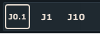
expr: "_jog_step=0.1" "J0.1" ""
;expr: "_jog_step=0.1" "J0.1" "" -> we assign value of 0.1 to a a jog step parameter. So when this button will be pressed, parameter will be assigned the value of 0.1 and when jog step will be used,
;machine will move in 0.1 distance increments.
expr: "_jog_step=1" "J1" ""
expr: "_jog_step=10" "J10" ""
Example 2: Since having multiple buttons for same parameters is somewhat space consuming, user can create menu button. Like name suggests, menu button will open a menu, where user can select desired menu item.
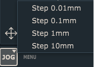
This example uses expr:
expr: "_jog_step=val" "JOG" typ=menu val="0.01@Step 0.01mm|0.1@Step 0.1mm|1@Step 1mm|10@Step 10mm"
;This example shows how to assign different values to jog step parameter using menu button. Menu will offer different values available as menu items.
;User can then select the item and assign new jog step parameter value.

;typ=menu -> this set the button type as menu button

;Val->  variable which will inhibit different values, based on which button menu item will be selected

;val="0.01@Step 0.01mm|0.1@Step 0.1mm|1@Step 1mm|10@Step 10mm" ->
;0.01@Step 0.1mm -> The value before @ symbol will be used as a value which will be assigned to val variable and consequently used as a new jos step value. All text after symbol @ will be displayed as menu item text.
;We use "|" symbol to divide each menu items properties.
This example uses cmd command:
cmd: "Jog.Jog_Step.Set" "JOG" typ=menu val="0.01@Step 0.01mm|0.1@Step 0.1mm|1@Step 1mm|10@Step 10mm"
;val is assigned directly to the Jog.Jog_Step.Set command
Buttons for PWM duty cycle values
Example 1: This example describes how to create a set of buttons for different PWM duty cycle values.
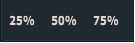
We can use the outpwm() expression function. When using expression function outpwm(), zero based numbering is used (1st pin has number zero, 2nd pin has number one etc…)
expr: "outpwm(0, 25)" "P25"
;expr: "outpwm(0,25)" -> sets the the duty cycle of first PWM output pin at 25%. First argument of out() function is PWM output pin number, second is duty cycle value in %.
expr: "outpwm(0, 50)" "P50"
expr: "outpwm(0, 75)" "P75"
Or we can use the Machine.Output_PWM command with Val and expr arguments:
cmd: "Machine.Output_PWM" val=[0;expr:(0+75)] name="75%"
; val will be consisted from two parameters. First is the number of the PWM output pin (mind the zero based numbering) and second one, in this case is, the value of duty cycle that is calculated
;using an expression. For this example we used simple and straightforward expression of addtion 0+75. So, Machine.Output_PWM command is assigned the value consisted from output pin number and duty cycle value.

cmd: "Machine.Output_PWM" val=[1;expr:(0+50)] name="50%"
cmd: "Machine.Output_PWM" val=[5;expr:(0+25)] name="25%"
Example 2: Since having multiple buttons for the same PWM output pins is somewhat space consuming, user can create menu button. Like name suggests, menu button will open a menu, where user can select desired menu item. In this case, menu items will be different values of duty cycle for output pin 6:
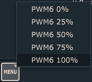
cmd: "Machine.Output_PWM" "MENU" stroke=1.1 typ=menu val="[5;0]@PWM6 0%|[5;25]@PWM6 25%|[5;50]@PWM6 50%|[5;75]@PWM6 75%|[5;100]@PWM6 100%"
;This example shows how to assign different values of PWM duty cycle of PWM output pin, using menu button. Menu will offer different values available as menu items.
;User can then select the item and assign new duty cycle value.

;typ=menu -> this sets the button type as menu button

;Val-> variable which will inhibit different values, based on which button menu item will be selected
;val="[5;0]@PWM6 0%|[5;25]@PWM6 25%|[5;50]@PWM6 50%|[5;75]@PWM6 75%|[5;100]@PWM6 100%" -> [5;0]@PWM6 0% -> The values within the []brackets before @ symbol, will set the PWM output pin number and value of duty cycle in %.
These values will be assigned to val variable and consequently used as a new duty cycle value for selected output PWM pin. All text after symbol @ will be displayed as menu item text.

;We use "|" symbol to divide each menu items properties.
We recommend using expression function: cmdlist()
What this expression does is, it will display all commands (menu items) from File, View,Program,Machine and Help menus.
So, you can type into the MDI window:
=cmdlist()
Software will display the list in the Output window of PlanetCNC TNG software.
Another thing that is very useful is PlanetCNC TNG G-code reference manual. User can find all parameters, functions, gocdes which could be useful when creating and configuring custom buttons.