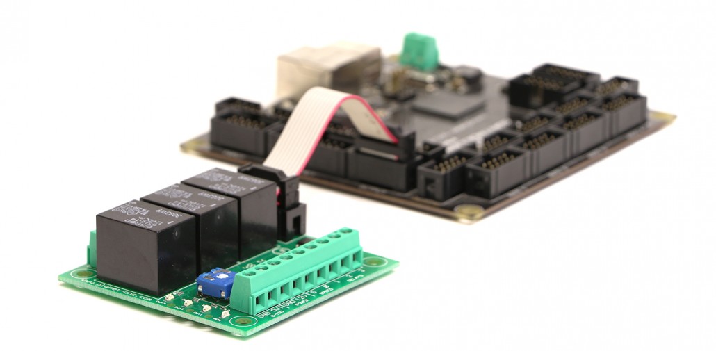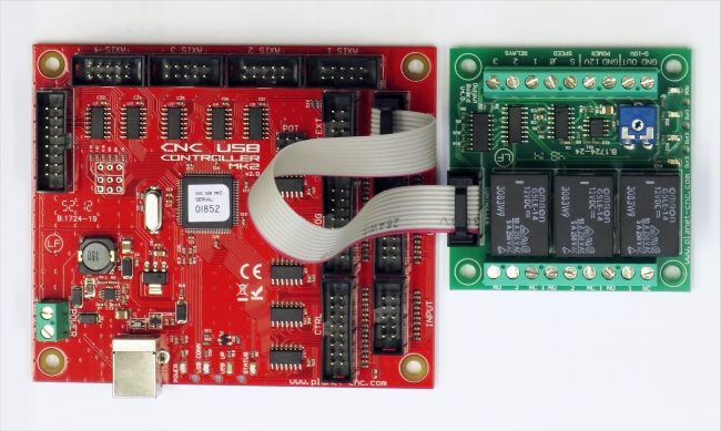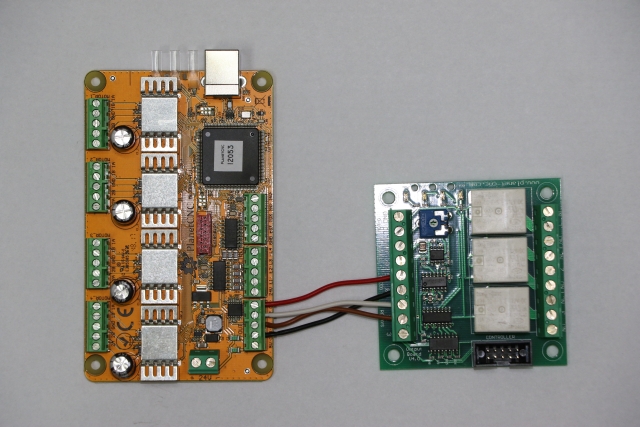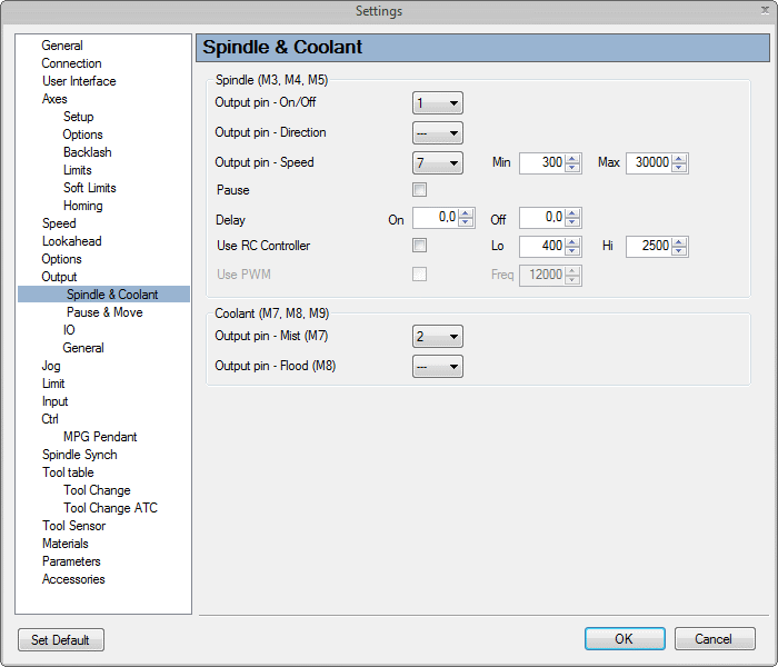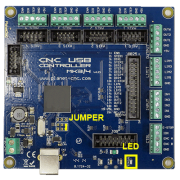
Using output board for spindle control
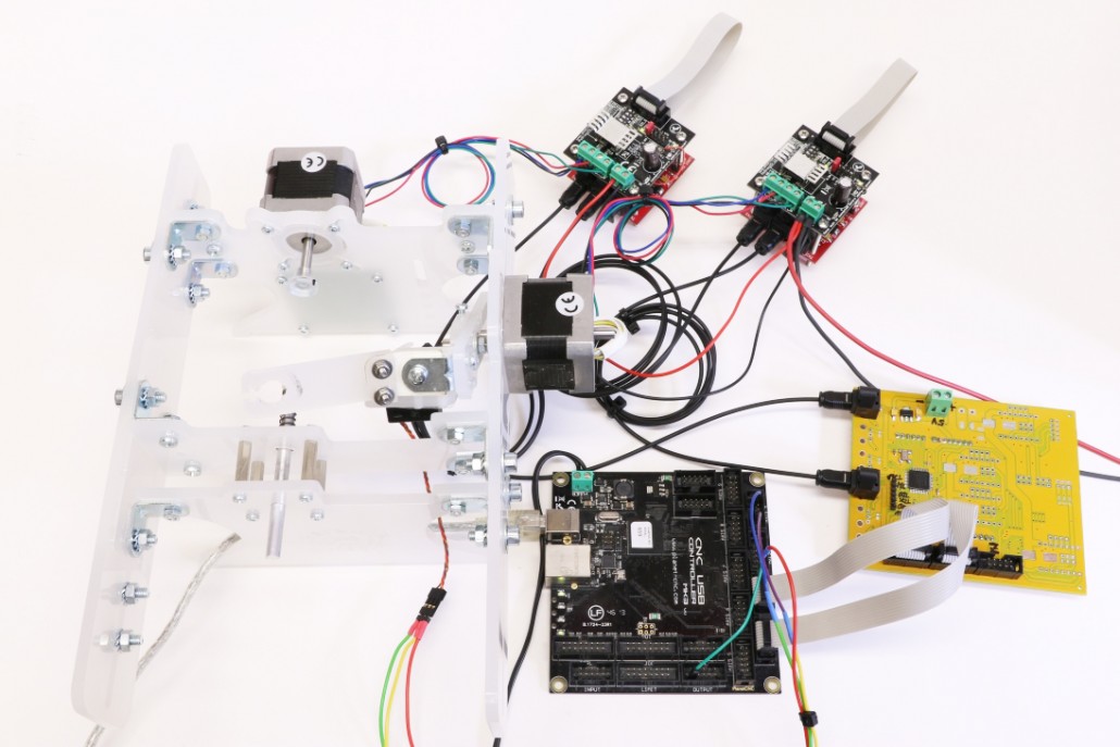
In this tutorial we will explain how to use output board with VFD and spindle. We will describe how to set VFD* parameters and how to connect output board with VFD control inputs.
We are aware that many users use different VFD’s but no worries, the work flow in a sense should be the same.
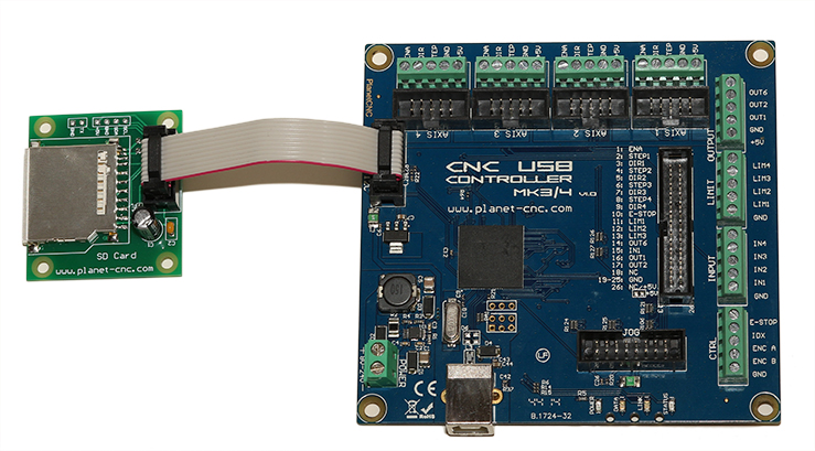
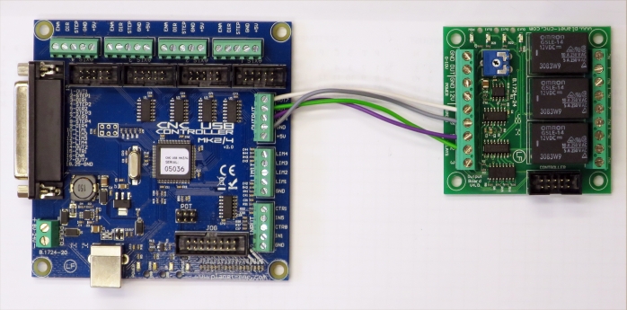
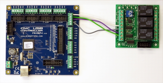
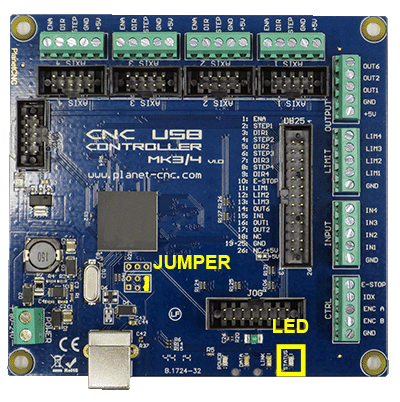
*For purposes of this tutorial we will use MK3/4 controller and Chinese Huanyang VFD which is a well known piece of equipment among hobby machinists around the world.
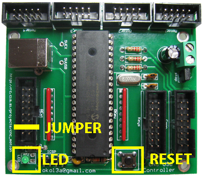
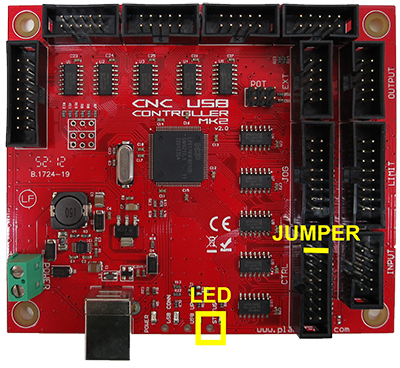
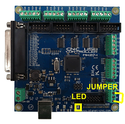
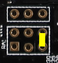
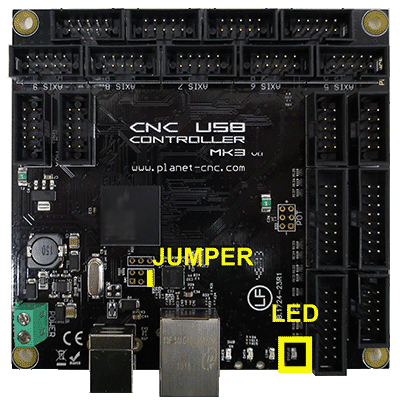
Please follow this link to introduce yourself with output board and controller pin configuration:
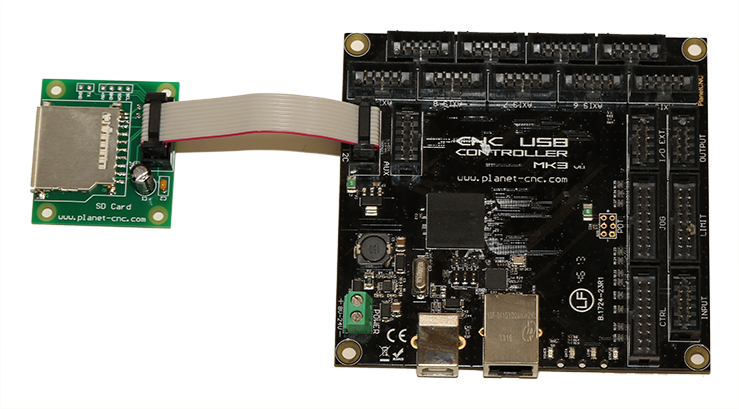
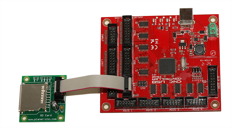
Using output board with PlanetCNC controllers
Step 1: Configuring Huanyang VFD’s parameters
Variable Frequency Drive (VFD) drives an electric motor by varying the frequency and voltage supplied to the electric motor. VFD controls motors ON/OFF control,speed, direction etc..
All these functions can be controlled via external equipment (output board). Output board communicates with VFD trough its control inputs which are located on external terminal panel.
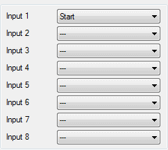
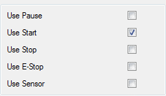
So first we need to define operating mode and configure VFD’s control inputs.
1.1: Defining VFD’s operating mode:
- We want to start/stop spindle from VFD’s external terminal panel
- We want to change motors direction from VFD’s external terminal panel
- We want to regulate motors RPM from VFD’s external terminal panel with 0-10 analog voltage signal
After going trough VFD’s user manual we know that we need to configure these parameters:
“Source of Run Commands” ->parameter PD001
PD001 → set it to value 1 (Set by external terminals)
Start, stop, change direction and speed can now be controlled via screw type input terminal.
“Source of Operating Frequency”-> parameter PD002
PD002 → set it to value 1 (Set by external terminals);
Source of operating frequency signal type is determined with parameter PD070
PD070 → set to value 0 (0-10V)
Motor speed can now be controlled via screw type terminal using the 0-10V input.
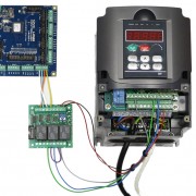
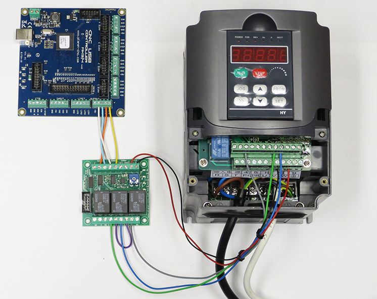
Step 2: Connecting output board with VFD
We need to connect output board with VFD control inputs.
Basic Connection Diagram :
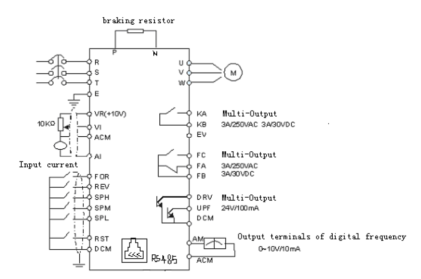
Control inputs of VFD that we will use:
“FOR”: This input will be used for forward motor rotation
“REV”: This input will be used for reverse motor rotation
“DCM”: Common Terminal of Digital and Control Signals
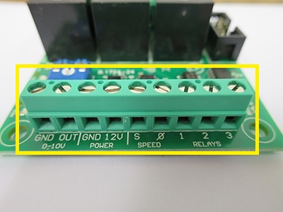
“VI”: Analog Voltage Frequency Reference Input. 0-10V signal from output board will be connected to this input.
“ACM”: Common Terminal of Analog and Control Signals. GND signal from output board will be connected to this input.
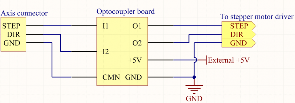
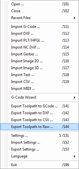
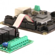
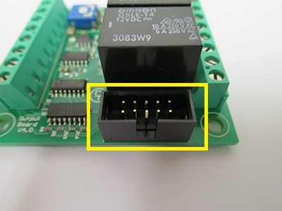
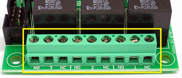
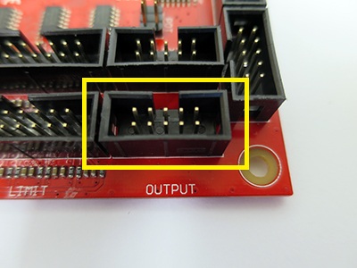
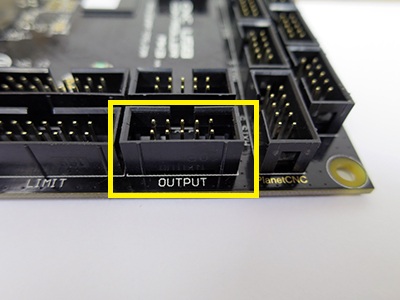
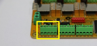
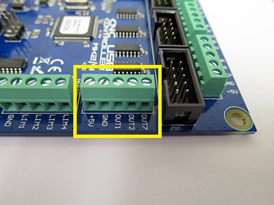
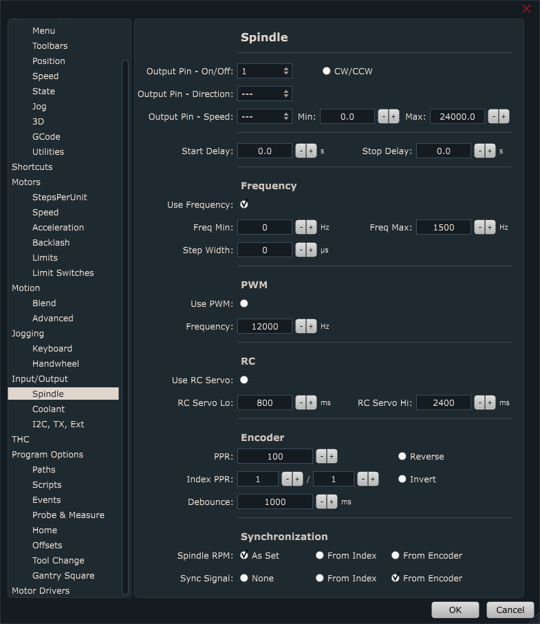
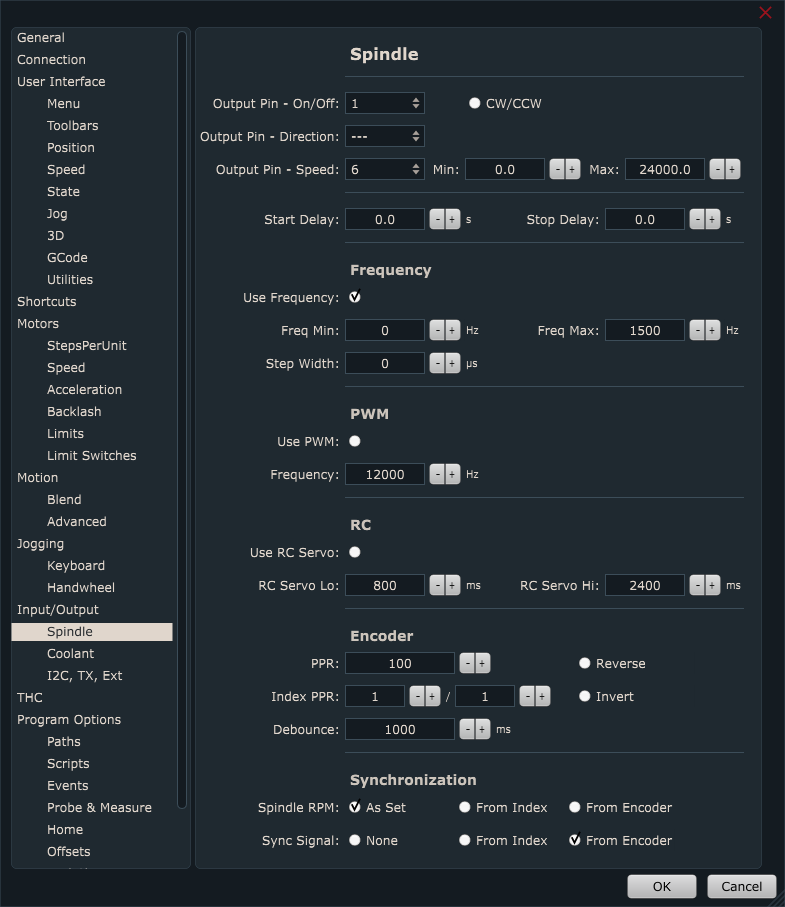
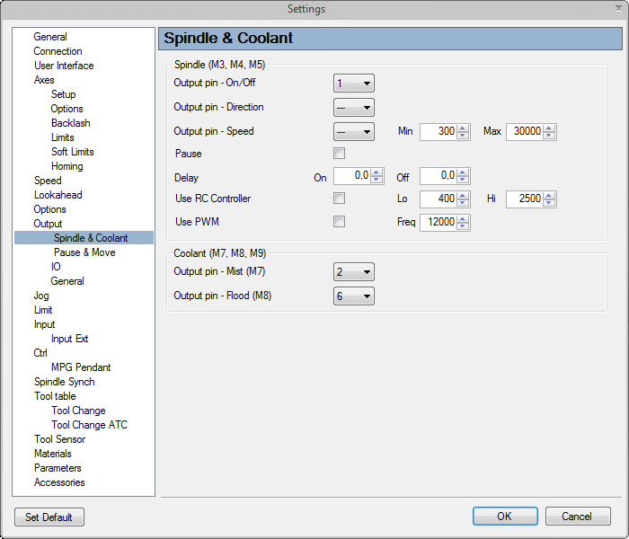
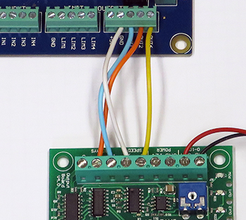
Connect output pins of controller with input pins of output board:
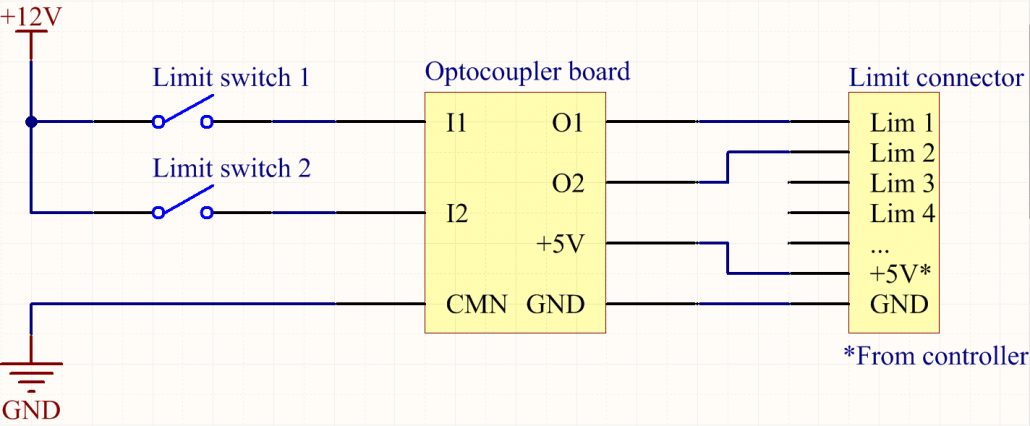
Connect output board with VFD’s control inputs:
Wiring diagram below illustrates how relays and varying voltage output are connected with VFDs control inputs so that we achieve on/off, direction and speed control:
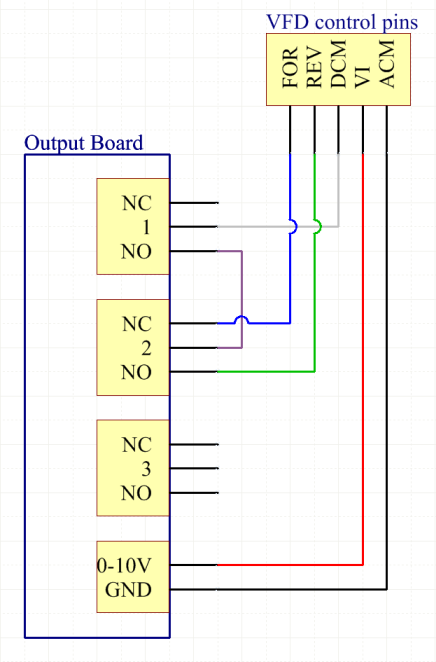
Short functional behaviour description:
When spindle is turned ON (M3 command), relay 1 is activated and motor rotates in forward direction(VFDs FOR input becomes active).
As soon as we change direction, relay 2 is activated and motor starts to rotate in reverse direction (VFDs REV input becomes active).
Please NOTE:
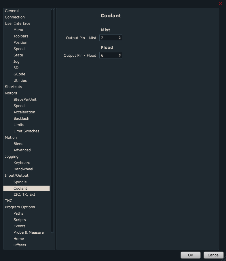
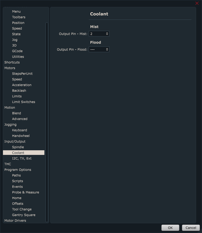
Before any wiring is done and equipment is connected, please check that all spindle, coolant and speed g-codes activate correct corresponding relays and outputs.